

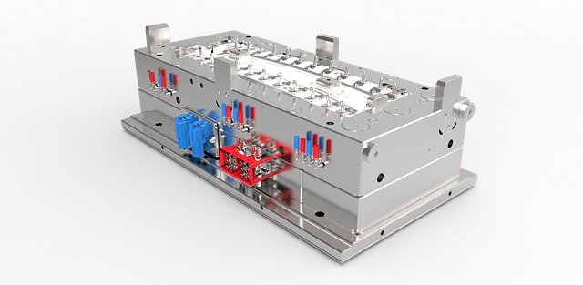
Cospa pushes 3D mold design past the drawing board
When Cospa, a mold maker in Italy’s Scame Group, moved its tooling work into Siemens NX, the goal was straightforward: shorten injection mold development without compromising on complex thermoplastic parts. The company reorganized its design office around digital workflows, assigning a project leader who can break a job into modular tasks for several designers working in the same environment.
Instead of individual engineers rebuilding geometry and mold bases in separate systems, Cospa now drives the entire tool from a 3D part model and associative assemblies. CAM programs are generated directly from the same data, cutting the time spent translating drawings and checking for mismatches. In the case study, Cospa reports that its CAM operations became about 50% faster after the change, because machining paths update automatically when mold components are revised.
For a trade shop that builds tools for thermoplastic parts across multiple end markets, this is not a cosmetic gain. Shorter CAM cycles mean less waiting between design sign‑off and steel cutting. It also means fewer scrap blocks created when a late change forces manual reprogramming. Cospa’s move is a practical example of digital mold design paying off in the part of the process most processors feel directly: how soon a new tool arrives on press.
Case galleries show digital work becoming standard practice
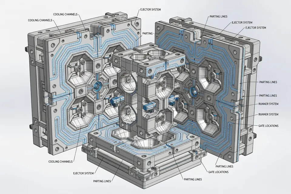
Cospa is not the only shop treating 3D design as its primary language. Spark Mould, an injection mold maker with a broad export portfolio, presents its work through a case gallery built around plastic part geometry, gating concepts and detailed tool layouts. The way those projects are documented suggests that CAD data, not paper sketches, now anchors customer conversations. Complex cases—such as multi‑cavity consumer goods molds—are illustrated with full cavity and core arrangements, cooling channel paths and parting line details.
Similarly, Chinese mold maker Gud Mould uses its technical news pages to walk through mold design topics step by step, from gate sizing and runner balance to steel selection and vent placement. Although the article language focuses on fundamentals rather than specific software brands, the guidance consistently assumes designers are working inside a 3D environment where flow analysis, shrinkage, and warpage can be reviewed against the model.
For processors, these examples matter because they show what you can reasonably ask of a supplier. Shops that present work in full digital detail usually have the ability to share native CAD, maintain revision history and support design reviews that look directly at flow paths and cooling, not just general arrangement drawings.
Troubleshooting ties back to the digital tool
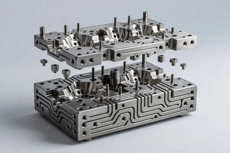
Digital design does not remove molding defects, but it changes how root causes are found. A recent case study from Efficient Innovations chronicles troubleshooting on a toothpaste packaging project where cosmetic defects initially appeared to be a hot‑runner problem. Standard process adjustments could not eliminate crown flash, so the investigation widened to include thermal behavior, valve pin design, cavity surface finish and part geometry.
The team eventually found that competing adhesion forces between polypropylene, the polished cavity and the heated pin tip during mold opening were driving the defect. The fix was physical—micro‑blasting the cavity surface to improve release—but the way the problem was framed depended on understanding the tool as a system, not just a set of machine parameters.
Efficient Innovations carries that same mindset into its structured defect analysis service, where common issues such as flash, sink marks, voids and weld lines are tied directly to mold alignment, pressure settings, cooling and gate design. The company promotes 24–48 hour defect diagnostics, a turnaround time that only makes sense when customers can supply complete mold and part data quickly. In practice, that means a clean digital definition of the tool.
"Effective injection moulding troubleshooting cannot rely on one proven approach alone. It requires analysing the complete system and understanding how multiple factors interact." - Efficient Innovations case study team said
For plant engineers, this reinforces the link between the CAD model and the floor: if the mold’s cooling circuits, venting, steel conditions and moving elements are not captured accurately, outside troubleshooters are blind to half the system.
Design of molds: simulation and weight reduction
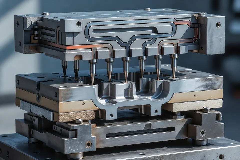
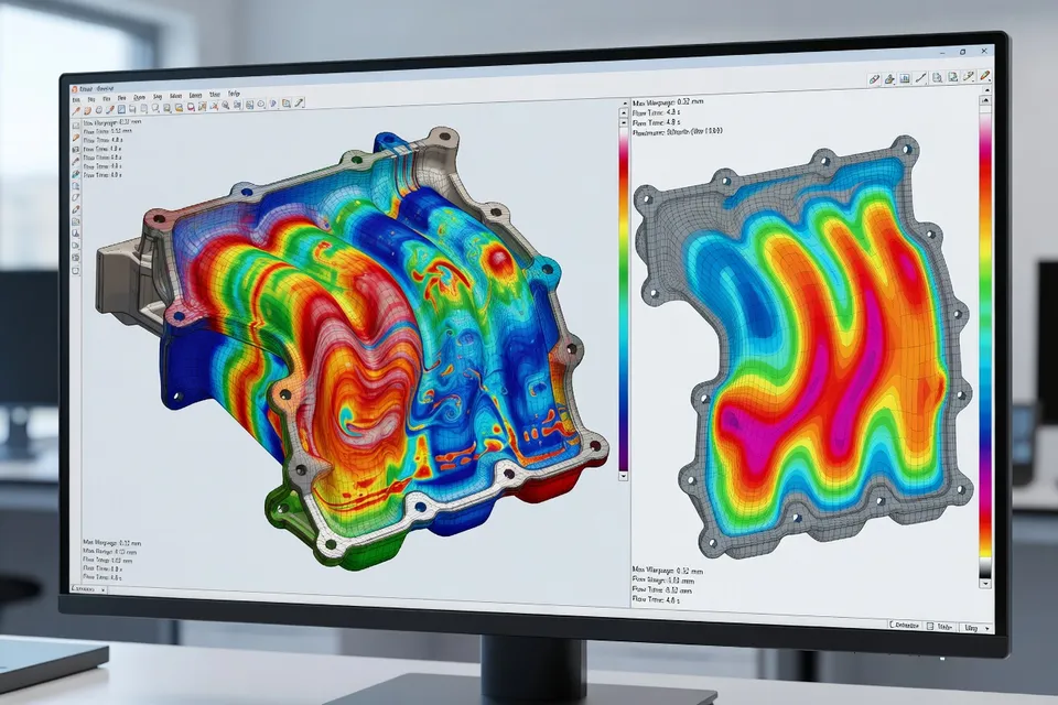
PlasticPortal aggregates expert articles and company listings around mold design, analysis and high‑speed injection molding, and the picture there is consistent: modern tooling work starts with digital validation. A multi‑part series on thermoplastic injection molding and weight reduction, for example, lays out a pre‑production sequence that runs from defining part requirements and designing the plastic geometry through flowability analysis, simulation calculations and rapid prototyping before any production mold is built.
The same article stresses that the constructability of the part is inseparable from mold design. Wall thickness, ribs, and transition radii must be set with warpage and filling behavior in mind, and those decisions are checked by simulation before a tool design is frozen. From there, prototype tooling and test shots are used to validate both weight and performance, and only then is a full production mold justified.
This approach directly supports processors chasing cycle time and material savings. When weight reduction is handled through iterative digital design and simulation, the risk of under‑packed sections, sink marks or poor weld line strength can be managed before steel is cut. That reduces both launch delays and the need for emergency tool rework.
What faster digital mold work means on the plant floor
For molders and brand owners, the shift to integrated 3D mold design and analysis changes how tooling projects are planned and run.
-
Lead time: Cospa’s report of roughly halving CAM programming time shows how a fully digital chain compresses the interval between design release and machining. Plants waiting on new tools feel this as weeks saved on project schedules.
-
Data access: Suppliers like Spark Mould and Gud Mould who present detailed mold layouts and case histories are effectively telling customers to expect full digital documentation. That makes internal troubleshooting, maintenance planning and future engineering changes more straightforward.
-
Quality control: Structured troubleshooting services built on complete tool data, such as Efficient Innovations’ 24–48 hour diagnostics, rely on well‑maintained digital records, not just that day’s machine settings. Process technicians can match shop‑floor symptoms to specific design features and get targeted corrective actions.
-
Energy and material use: The PlasticPortal focus on weight reduction within digitally validated designs shows where future pressure will come from: cutting resin usage while keeping quality, backed by simulation and prototype loops.
The next practical step for a processor or converter is simple: ask your toolmakers how they manage their design data and what simulation and troubleshooting practices they tie to that model. As Cospa’s experience and the case histories from Spark, Gud and Efficient Innovations show, the shops that live inside a digital tool definition are already delivering faster CAM work, cleaner root‑cause analysis and more predictable mold launches.
Editorial Insights
- How does fully integrated 3D mold design fundamentally change the way tooling projects are planned and executed?
- Integrated 3D design shifts tooling from a sequential, drawing‑driven process to a connected data model where part geometry, mold layout, CAM and analysis are all associatively linked. This reduces hand‑offs, shortens rework loops and makes late design changes manageable because machining paths and documentation update from the same source. On the planning side, it turns mold development into a more predictable, milestone‑based process where design freeze, simulation, machining and troubleshooting are coordinated around one digital definition of the tool.
- What are the main sustainability implications of moving weight‑reduction and mold optimization into a digital, simulation‑driven workflow?
- When weight reduction is handled through simulation and iterative digital design, resin savings can be pursued without blindly cutting wall sections or ribs. Potential defects like warpage, sink and weak weld lines are identified before steel is cut, which curbs scrap, emergency tooling rework and unnecessary trial shots. Over time, this data‑driven approach supports leaner part designs, shorter cycles and lower energy use per part, making efficiency gains repeatable rather than one‑off improvements.
- Why is high‑quality digital mold data becoming a strategic asset rather than just an engineering convenience?
- Clean, structured mold data underpins faster CAM programming, accelerated defect diagnostics and more reliable maintenance planning, which directly affect time‑to‑market and uptime. As tooling portfolios grow, the ability to search, compare and reuse proven layouts, cooling concepts and gating strategies becomes a competitive advantage, not merely good housekeeping. For management, this turns the design database into a lever for cost reduction and risk control across multiple programs, rather than an isolated technical repository.
- How does the shift to system‑level defect analysis reshape expectations for troubleshooting molded parts?
- System‑level analysis treats defects as the result of interactions between part geometry, gating, cooling, steel condition and process settings, rather than symptoms to be chased with machine adjustments alone. This perspective demands complete digital descriptions of the tool and part so that root causes can be traced to specific design features and thermal behavior. As it becomes standard, plants will expect faster, more conclusive diagnostics—but they will also need to invest in capturing and sharing accurate mold data to make those services viable.
- What ethical considerations emerge as processors rely more heavily on digital tools and automation in mold development?
- As more decisions are embedded in simulations and automated workflows, there is a responsibility to ensure models reflect real‑world behavior and do not mask risks in favor of speed or cost. Over‑reliance on automation can erode hands‑on expertise, making plants vulnerable when digital assumptions fail or incomplete data drives the analysis. Ethically, there is also a duty to use these tools to minimize waste and defects, not just to accelerate launches, tying digital investment to broader performance and sustainability outcomes.
- How might increased transparency in digital mold layouts change relationships between processors and their tooling suppliers?
- When suppliers routinely share full 3D layouts, gating concepts and cooling circuits, the conversation shifts from black‑box tools to collaborative engineering. Processors gain the ability to scrutinize design choices, align molds with internal standards and plan future modifications with fewer surprises. This level of visibility can strengthen trust but also raises expectations: once customers are used to accessing native CAD and revision histories, anything less feels like a step back in both technical maturity and accountability.
References
- 1.Siemens. Home | Global | Siemens. Siemens.
- 2.Siemens Digital Industries Software. Developing injection molds gets easier – and faster – with the help of 3D design software. Siemens Digital Industries Software.
- 3.ANTEC® 2026. Sustainable Tire Rubber - A Comparison of Silica and Carbon Black Filled Tread Compounds Using Dynamic Mechanical Analysis (DMA). Swapcard.
- 4.Spark Mould. Mould case. Spark Mould.
- 5.Gudmould. News. Gudmould.
- 6.Efficient Innovations. Injection moulding troubleshooting. Efficient Innovations.
- 7.HTI Plastic. Manufacturing news feed. HTI Plastic.
- 8.PlasticPortal. PlasticPortal.