

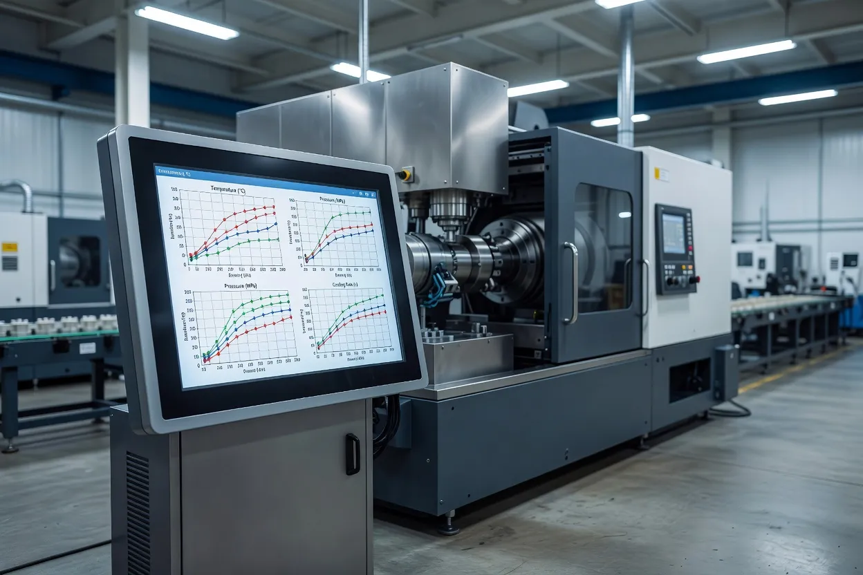
Bay Tech Plastics described its scientific-molding approach on Oct. 1, 2026, around a familiar production problem: a molded part can fail after small changes in temperature, pressure, or cooling time. The company listed sink marks, splay, warpage, and short shots among the defects that can affect complex components for automotive tier-two assemblies, medical devices, and electronics.
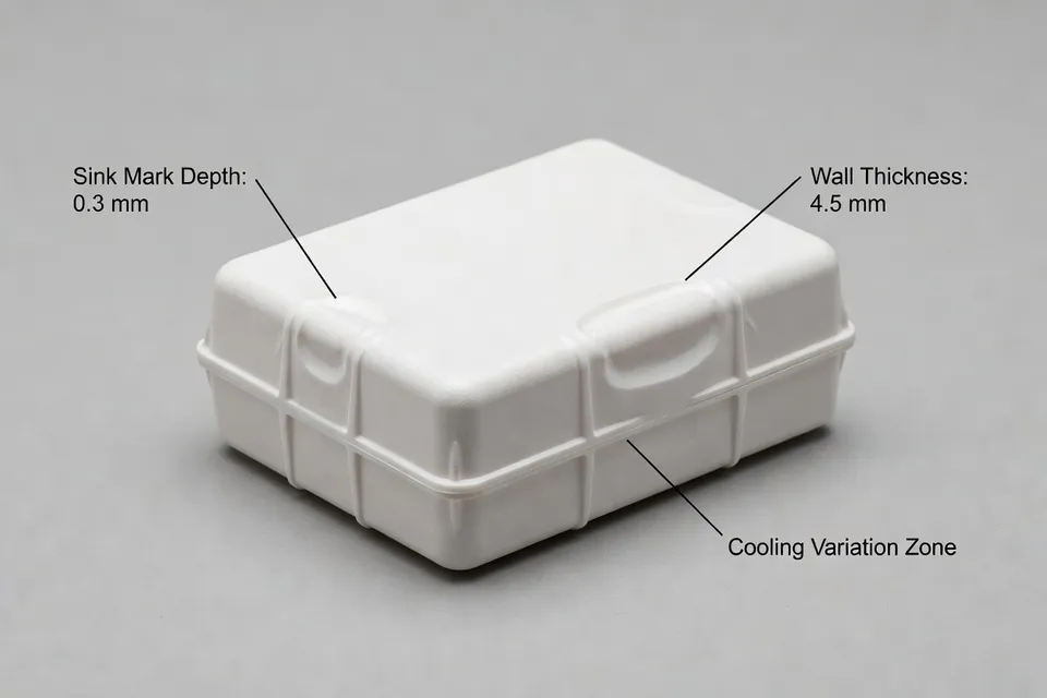
The useful shift is from naming the defect to isolating the process variable. A sink mark is not a setting. Warpage is not a root cause. Each is an observed result that must be connected to filling, packing, cooling, mold temperature, material behavior, or part geometry before a processor changes the machine recipe.
The supplied sources cover that same control problem from different angles. They include a plastics-processing guide to mold-flow analysis, an engineering study, a technical paper, a warpage case, a scientific-molding discussion, and material on hot-runner mold design. They do not establish one common plant trial, one polymer, or one shared production baseline. The evidence supports a method for narrowing causes, not a universal defect-reduction percentage.
Start with the part and the failure mode
Bay Tech’s news item places the problem in high-precision molding, where small process changes can produce quality variation. Its examples matter because the defects do not carry the same diagnostic path. A short shot points first toward incomplete filling, restricted flow, insufficient pressure, inadequate temperature, or an incorrectly balanced process window. A sink mark raises a different question about packing and local shrinkage. Splay can require attention to moisture, volatile material, shear, or processing conditions. Warpage requires comparison of shrinkage and cooling across the part.
The operator therefore needs a stable object of comparison: the same part, material, mold, machine, and measurement method. A visual inspection alone can identify a failure, but it cannot establish whether the defect moved after a parameter change. QA needs a defined acceptance limit, while process engineering needs the actual settings and the time at which the part was produced.
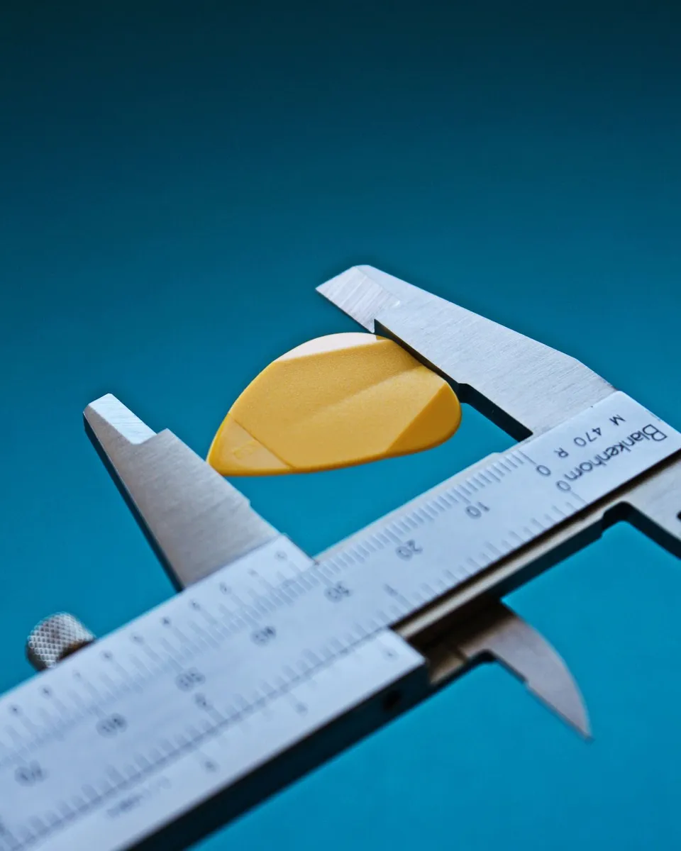
The source packet does not provide a shared numerical baseline for these defects. It does not show a common before-and-after scrap rate, cycle-time change, or capability result. Those cells remain open rather than being replaced with a generic claim that simulation improves quality.
Use simulation before changing the recipe
Mold-flow analysis is most useful before the team starts changing several machine settings at once. The supplied SolidWorks plastics material describes injection-molding simulation as a way to examine filling, packing, cooling, and warpage-related behavior before or during tool development. That sequence gives the team a map of where the melt is expected to go and where pressure, temperature, weld lines, air, or uneven cooling may create risk.
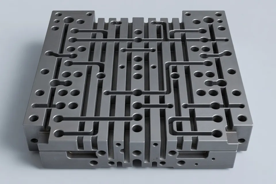
A processor can use that map to assign a test to a physical cause. If the predicted flow front hesitates near a thin section, the trial can examine fill speed, melt temperature, gate condition, or venting while holding other factors constant. If the analysis points to uneven cooling, the tool team can inspect cooling-channel layout and compare measured mold temperatures rather than asking the operator to compensate indefinitely with packing pressure.
Simulation does not close the loop by itself. It predicts behavior from the geometry, material data, boundary conditions, and selected process inputs. The press still has to make the part, and the plant still has to measure the result. A predicted warpage pattern becomes production evidence only after the molded part is measured against the same coordinate system and acceptance requirement.
Treat warpage as a measurement problem
The MoldMaking Technology material on warpage with windage shows why a defect investigation must include the tool, the part, and the measurement method. Warpage can result from unequal shrinkage and cooling, but the plant must still determine where the part moved, how much it moved, and whether the result is repeatable across the cavity or across the run.
A useful trial records the cavity, resin lot, machine settings, mold temperatures, cooling time, and part age at measurement. It also distinguishes a dimensional failure from a cosmetic observation. A part that appears twisted may pass one visual check and fail a fixture, gauge, or coordinate measurement. The method chosen by QA determines which change counts as an improvement.
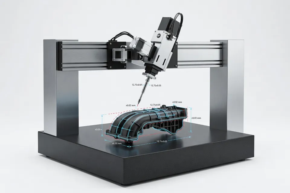
The sources do not supply a common warpage value that can be transferred to every mold. They support a narrower instruction: connect the simulation output to a defined dimensional measurement, then retain the failed parts and the settings that produced them.
Keep the mold hardware in the control discussion
The hot-runner material in the packet adds another object to the troubleshooting chain. Gate location, runner balance, component selection, and thermal behavior influence how the melt reaches the cavity. A machine recipe cannot compensate reliably for a tool that distributes heat or pressure unevenly.
That distinction assigns ownership. The processor controls the approved operating window and the recorded recipe. The mold builder controls the flow path, cooling arrangement, venting, and hot-runner details within the tool design. The resin supplier controls material guidance and lot information. QA decides whether the part meets the release criteria. When a defect remains after a parameter change, the next action may belong to tool maintenance rather than production adjustment.
A hot-runner or mold redesign is not the same event as a validated production improvement. The packet describes design and partnership mechanisms, but it does not provide a single shared production result for all the cited applications. The plant must still verify start-up stability, cavity balance, temperature uniformity, and part dimensions.
Convert the analysis into a controlled trial
A processor can turn the sources’ mechanisms into a trial sheet without treating simulation as an automatic answer:
- Record the defect, cavity, resin lot, machine, mold temperature, melt temperature, fill profile, packing settings, cooling time, and cycle time.
- Select one suspected mechanism, such as incomplete filling, local packing loss, moisture, or uneven cooling.
- Change one controlled input or one defined group of linked inputs, and retain the original condition as the baseline.
- Measure the part with the method that QA uses for release, not only with a visual check.
- Compare the result with the predicted flow, pressure, cooling, or deformation pattern.
- Refuse the setting if it reduces one defect but creates a short shot, flash, dimensional failure, longer cycle, or another out-of-spec condition.
This sequence keeps the improvement claim proportional to the evidence. A simulation study can narrow the test. A molding trial can show whether the predicted mechanism appears on the press. A capability study or repeated production run can establish whether the setting remains stable.
The next checkable event is a controlled trial lot in which the plant records the predicted defect location, the selected parameter change, the measured part result, and the QA release decision. Until that record exists, simulation remains a parameter-selection tool rather than proof of a closed-loop production result.
Editorial Insights
- When should a processor stop adjusting machine settings and inspect the mold instead?
- Inspect the gate, runner balance, vents, cooling channels, and hot-runner temperature uniformity when the defect persists after a controlled parameter trial. A recipe cannot reliably correct uneven melt distribution or cooling, although operators often keep increasing packing pressure because it is faster than opening a tool-maintenance action. Verify cavity balance, measured mold temperatures, and part dimensions before approving a mold change as a production improvement.
- What must be fixed before simulation results can guide a molding trial?
- File the actual part geometry, material data, mold layout, process inputs, and boundary conditions used in the model, then compare them with the press and tool on the floor. If the model uses nominal temperatures or an assumed fill profile while production runs with different values, its predicted pressure, cooling, or warpage pattern is only a starting point. Keep the original settings as a baseline and change one suspected cause at a time.
- How should a plant prove that a warpage adjustment improved the part rather than the inspection?
- Measure the same feature with the same fixture, gauge, or coordinate method, and record cavity, resin lot, mold temperatures, cooling time, and part age. Visual appearance alone cannot show whether the part moved less or whether the inspection angle changed; a twisted part may pass a visual check and fail the release gauge. Compare repeated parts against the defined dimensional limit before changing the approved window.
- Can simulation establish a universal defect-reduction percentage for injection molding?
- No. It can narrow the likely mechanism and select a more efficient physical trial, but the article provides no shared polymer, mold, machine baseline, scrap rate, or capability result from which to transfer a percentage. Treat the prediction as evidence for what to test, not proof of production performance; the usual failure is claiming quality improvement after one visually acceptable sample.
- What belongs on the controlled trial sheet before changing a process window?
- Record the defect location, cavity, resin lot, machine and mold, melt and mold temperatures, fill profile, packing settings, cooling time, cycle time, predicted mechanism, measured result, and QA release decision. Define the acceptance limit before the run, because a setting that removes a sink mark but creates flash, a short shot, a dimensional failure, or a longer cycle is not an improvement. Repeat the condition sufficiently to establish stability rather than approving a single favorable part.
References
- 1.Baytech Plastics. (2026, October 5). News. Baytech Plastics.
- 2.China Plastics Exhibition. Abstract 5626. China Plastics Exhibition.
- 3.Jurnal Venus. Article 1628. Jurnal Venus.
- 4.Seawin Industrial. Mold flow analysis insights for curved IoT sensor enclosure. Seawin Industrial.
- 5.The International Journal of Advanced Manufacturing Technology. Article associated with DOI 10.1007/s00170-026-17702-9. The International Journal of Advanced Manufacturing Technology.
- 6.MoldMaking Technology. Taking aim at warpage with windage 2. MoldMaking Technology.
- 7.SOLIDWORKS. Plastics mold injection. SOLIDWORKS.
- 8.MoldMaking Technology. Hot runner mold component partnerships lead to innovative mold designs. MoldMaking Technology.