

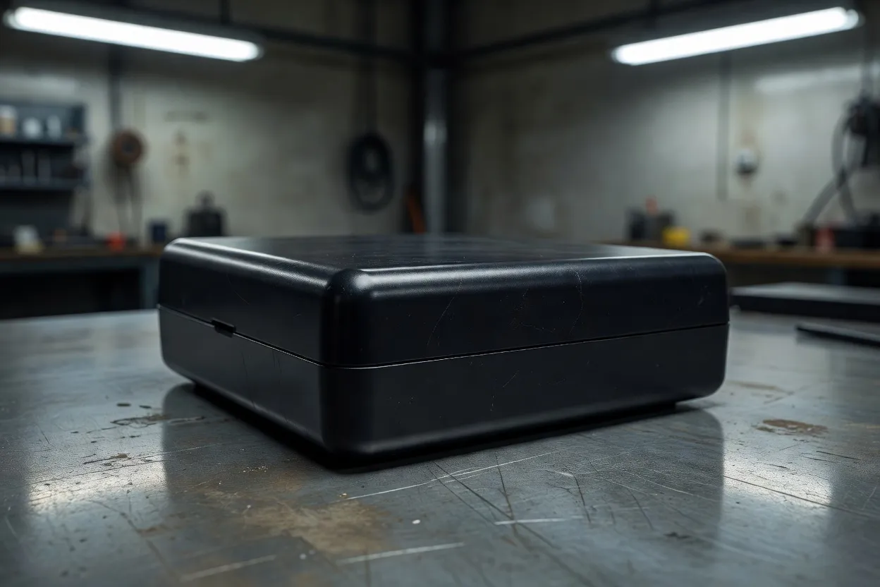
A weld line is the weak plane where separate melt fronts meet. The first check is not a cosmetic inspection. Find where the fronts divided, where they reunited, and whether that meeting point sits in a loaded section of the part. A gate placed near a hole, insert, boss, or other obstruction can force the melt to split and close around it. The line may look like a scratch. It is not one.
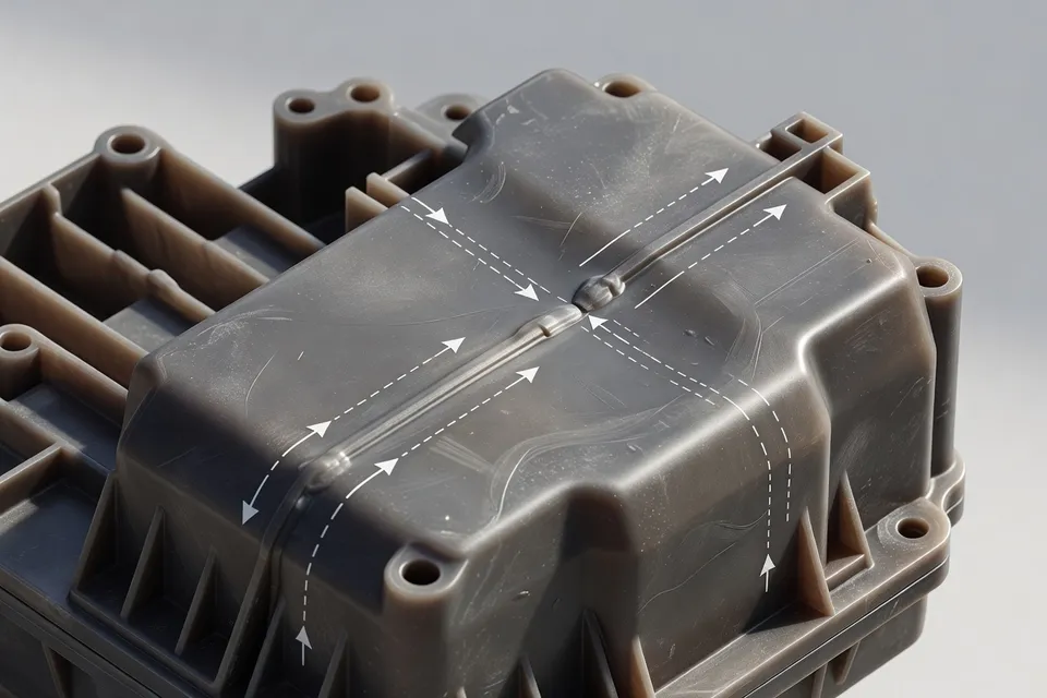
The control plan is straightforward: put the gate where the part fills cleanly, vent the meeting plane, and keep both fronts hot enough to fuse before the interface freezes. That sequence is useful only when the polymer, mold geometry, and process window stay the same. It is not a universal setpoint rule.
The gate sets the failure location
Texas Injection Molding's design guidance places the gate in the area that fills the part best, often the thickest section, while keeping it away from high-stress or impact regions. That is the right first decision because the gate controls the flow path. A single gate feeding a part with a core pin can send the melt around the pin and create a weld line on the opposite side. Multiple gates can improve filling, but each split creates another meeting condition that must be checked.
JBRplas identifies three practical design moves: move the weld line away from the load path, shorten the flow distance before the fronts meet, and use no more gates than filling requires. That gives the setter a boundary. If the weld line is in a snap-fit arm, a fastener boss, a pressure wall, or another known load path, process adjustments are not the first fix. The mold or gate layout needs review.
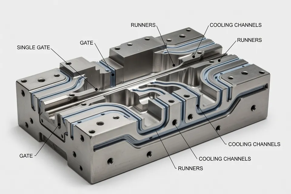
The part designer also has to account for holes, bosses, inserts, ribs, and wall changes. Texas Injection Molding recommends using flow analysis to identify possible knit-line locations and to direct those lines away from high-stress areas. Simulation can locate the meeting plane. It cannot, by itself, prove that the molded part will survive service.
The vent is the first line-side check
Air trapped where two fronts meet can prevent proper fusion and can add burn marks, short shots, and excessive injection pressure. Check the vent at the predicted meeting plane before increasing pressure. A blocked or shallow vent changes the cavity condition even when the machine settings have not moved.
Venting may use parting-line channels, ejector pins, vent pins, or runners. Texas Injection Molding notes that vent pins become necessary when parting-line venting cannot remove gas from the required geometry. M. Holland's defect guidance makes the maintenance point plainly: trapped air needs a path out, and cleaning the mold and ejector pins can restore natural venting. A weld line that appears after a mold-cleaning interval should trigger that inspection before a material change.
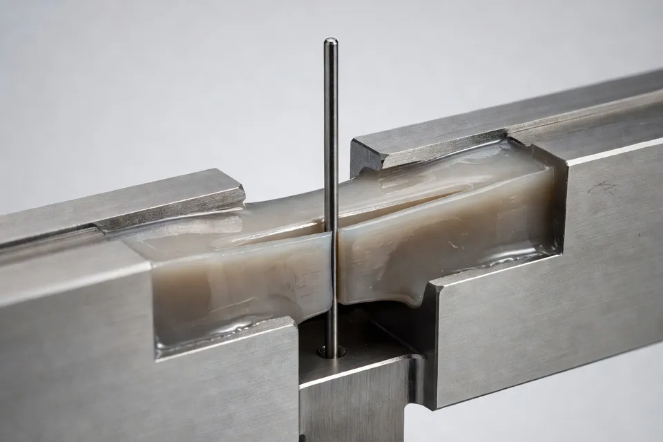
The technical references do not establish one vent dimension for every resin and mold. JBRplas gives typical values of 0.02–0.03 mm for unfilled materials and 0.01–0.015 mm for low-viscosity materials such as PA6. Treat those as the stated examples, not as a shop-wide cut depth. The resin grade, viscosity, filler, steel condition, and flash limit still control. If the material or vent condition is different, the check is incomplete.
Temperature and speed affect the joining window
The fronts must remain hot long enough for molecular diffusion across the interface. A hotter mold and hotter melt can extend that window, while a long flow path gives the fronts more time to cool before they meet. JBRplas reports that increased injection speed typically improves weld-line strength by 5–15 percent, but that figure is a reported general range, not a guaranteed result for a particular cavity.
Use the result as a verification prompt. If speed is changed, inspect the actual weld-line location and test the part under the required load. Do not carry the percentage into a different polymer, filler level, wall thickness, or mold without a comparison lot. The references support the mechanism, not a universal machine recipe.
| Reported condition or result | Value |
|---|---|
| Typical weld-line strength improvement from increased injection speed | 5–15% |
| Typical vent depth for unfilled materials | 0.02–0.03 mm |
| Typical vent depth for low-viscosity materials such as PA6 | 0.01–0.015 mm |
The values above are technical guidance reported by JBRplas, not a production acceptance table. The result that matters is the part made with the actual gate, resin, mold temperature, and vent condition.
What the machine check can and cannot prove
A setter can confirm whether the cavity fills consistently, whether the weld line has shifted, whether burn marks indicate trapped gas, and whether the vent or ejector-pin area is dirty. M. Holland recommends checking material delivery during filling and maintaining the first-stage fill and transfer process to reduce short shots and flash. That can stabilize filling. It does not remove a weld line created by an unavoidable flow split.
The same limit applies to overflow. M. Holland notes that allowing material to overflow at the knit-line location can improve meld, with the remnant removed during ejection or after molding. That is a local design solution. It is not permission to hide a weak weld line behind flash removal, and it does not replace a gate-location review on a high-liability part.
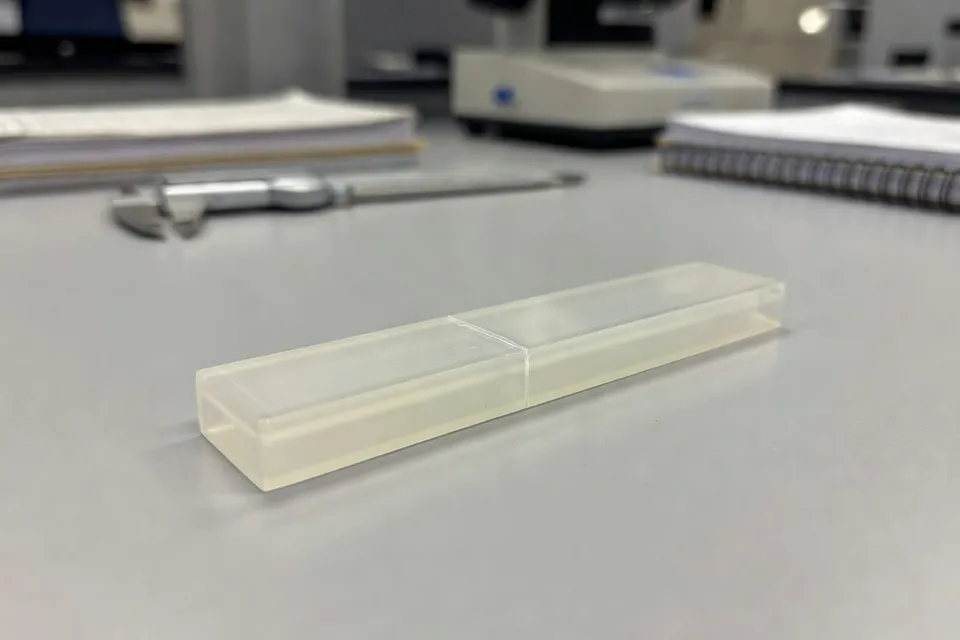
A weld line is not automatically a reject. It becomes a stop condition when it lies in a specified load path, when tensile, impact, or fatigue performance fails, when the line opens during inspection, or when the process change moves the defect without proving strength. JBRplas recommends molding tensile bars or representative plaques with the production gate configuration and testing the weld line directly. The simulation predicts location; testing predicts performance.
Stop the trial if the resin is changed, the material is wet, the mold is already at its temperature limit, or QA has placed the lot on hold. The supplied guidance does not define a common stop threshold for those conditions. That missing limit belongs in the control plan.
Before the next shift changes pressure, check the weld-line location against the load path, clean and verify the vent at the meeting plane, record the actual melt and mold temperatures, and compare one controlled sample against the approved part—not just against the appearance standard.
Editorial Insights
- When should a weld-line problem go back to mold design rather than machine settings?
- Refuse to tune around a weld line that sits in a snap-fit arm, fastener boss, pressure wall, or other defined load path. First map the line against the gate, holes, inserts, ribs, and wall changes; if the flow split itself places the interface in a loaded section, review the gate or feature layout before changing pressure or temperature. A faster fill can improve fusion, but it cannot move an inherently badly located weld line. Simulation can predict the meeting plane; it does not prove service strength.
- What should be checked before increasing injection pressure on a weld line with burn marks or short shots?
- Inspect and clean the vent, ejector-pin area, and last-to-fill region before raising pressure. Trapped air at the meeting plane can block fusion, create burn marks, and increase apparent filling resistance even when the machine setup has not changed. The usual mistake is to treat a blocked or shallow vent as a pressure problem; more pressure may only compress the gas harder and worsen the defect. Confirm the actual vent condition and steel alignment, then rerun a controlled sample.
- Can the reported weld-line improvement from higher injection speed be used as a production guarantee?
- No. The reported 5–15% improvement is a verification prompt, not an acceptance value. Change fill speed within the resin’s approved window, then inspect the actual line and test tensile, impact, or fatigue performance on representative parts. A poorly vented mold can trap air at higher speed, so the apparent gain from hotter, faster fronts may be cancelled by burning or incomplete fusion. Do not transfer the percentage between polymers, filler levels, wall thicknesses, or gate layouts without comparison data.
- What records are needed before approving a temperature change intended to strengthen a weld line?
- Record the actual melt temperature, mold temperature, fill profile, transfer point, resin grade, filler condition, and vent status against the approved setup. Then compare parts made before and after the change, with the weld line located and tested under the required load. A higher temperature can preserve the joining window and improve molecular diffusion, but it must remain inside the material’s processing limits. The common failure is approving a setpoint from the controller display while the cavity, resin moisture, or local mold condition is different.
- When is overflow at the weld line a legitimate design measure rather than a cosmetic fix?
- Use overflow only when it is deliberately designed to draw the meeting plane and trapped gas into a removable pocket, with the remaining part still verified for strength. It can improve local meld where the line cannot be relocated, but flash removal does not repair a weak interface by itself. File the overflow geometry, vent location, trimming method, and test result in the control plan. If the weld line remains in a specified load path, the gate layout still requires review.
- What should stop a weld-line trial before the next set of machine adjustments?
- Stop when the resin has changed, the material is wet, the mold is already at its temperature limit, or QA has placed the lot on hold. The trial should not proceed on appearance alone: verify the line against the load path, confirm the vent at the meeting plane, record actual temperatures, and compare a controlled sample with the approved part. The missing stop threshold is a control-plan gap, not permission for the setter to keep changing pressure, speed, or temperature until the defect looks less visible.
References
- 1.Texas Injection Molding. (2026, October 3). Plastic injection molding design guide. Texas Injection Molding.
- 2.JBRplas. (2026, October 9). Weld lines in injection molding — Formation, strength loss, and how to minimize them. JBRplas.
- 3.M. Holland. (2026, October 5). How to solve 10 common injection molding defects. M. Holland.
- 4.Depix AI. Weld line 2026: Where the material meets itself. Depix AI.
- 5.Toray Plastics. Amilan technical information. Toray Plastics.
- 6.Toray Plastics. Torelina technical information. Toray Plastics.
- 7.Polimery Journal. Article PDF. Polimery Journal.
- 8.BASF. Injection molding problems in engineering thermoplastics: Causes and solutions. BASF.
- 9.Eastman. Technical information. Eastman.
- 10.J-STAGE. Article PDF. J-STAGE.