


Air traps and under-cure do not belong in the same troubleshooting bucket. The first check is physical: find the last area to fill, then inspect the nearest vent, relief path, insert clearance, and vacuum connection. The second is chemical: compare the current compound's cure behavior with the approved baseline before changing press settings.
Rubber injection molding feeds uncured compound through a runner and gate into a closed heated mold. The rubber must fill without sealing off the escape path for displaced air, then develop its crosslinked network during the cure stage. That sequence makes the stop decision clear. A short shot, burn, void, or sudden pressure rise near the end of filling is not permission to keep raising pressure. Hold the run if the air path is blocked or if the pressure curve has moved outside the validated window.
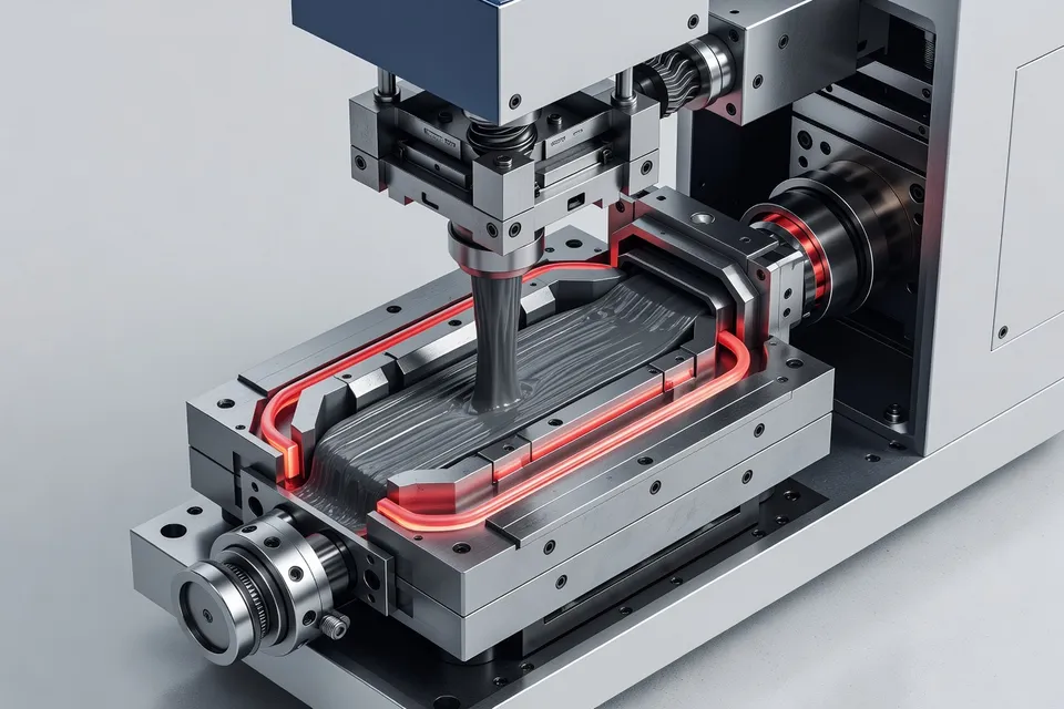
The last-fill point
Start with a short-shot check when the defect appears near a rib, blind pocket, insert, or the area opposite the gate. Samples made at several filling percentages show the flow-front direction and identify where the cavity actually finishes filling. That location—not the most convenient parting-line location—should govern the vent check.
A vent groove can be present and still fail. Cured rubber, mold-release residue, damaged lands, a blocked insert, or a restricted vacuum hose can close the escape route. Runner balance and gate restriction can also push the flow front into an area the original vent layout did not serve. The check is therefore broader than “vents open.” Confirm the parting surfaces are clean, the vent insert is clear, the ejector-pin vent moves, and the vacuum port and hose hold their repeatable condition.
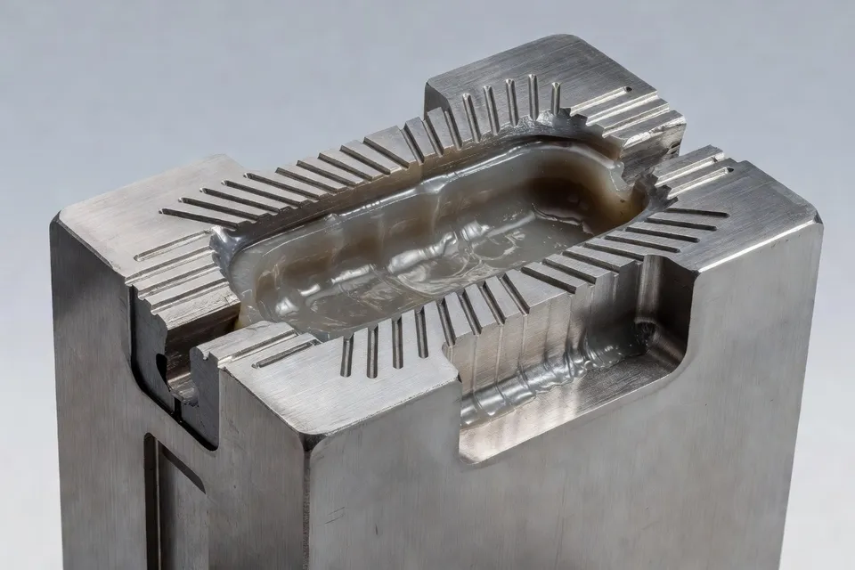
The vent has two jobs that pull in opposite directions. It must release air and process gas quickly enough to avoid a void or burn, but it must restrict rubber enough to keep flash within the approved limit. A larger or deeper passage is not automatically an improvement. Vent dimensions need a controlled trial using the production compound. A setup proven on one compound, geometry, or mold temperature does not travel automatically to another job.
The pressure curve
Record actual response, not just the values entered on the controller. Consecutive cycles should be compared using injection time, peak pressure, actual speed, shot weight, finished-part weight, flash, surface condition, internal voids, dimensions, and rejection rate. A pressure curve that rises sharply near the end of filling can point to trapped air or a flow restriction. A change in curve shape can also come from compound viscosity, a blocked gate, runner restriction, mold-temperature movement, feeding instability, or incorrect shot volume.
| Check across consecutive cycles | What the check can separate |
|---|---|
| Peak pressure and curve shape | Air restriction, gate restriction, viscosity shift, or unstable filling |
| Shot weight and finished-part weight | Feeding or metering variation versus cavity-fill loss |
| Flash, voids, and surface condition | Excessive pressure, blocked venting, or incomplete air removal |
| Injection time and actual speed | Control response versus the programmed setting |
The table is a diagnostic split, not a release specification. If the curve changes while weights remain stable, inspect venting, gates, mold temperature, and pressure response. If weights move with the curve, check feeding and shot volume before blaming the mold.

Reducing the final injection speed may give air more time to leave. It will not repair a damaged or clogged vent. Nor should an operator use a slower fill to hide a mold that has moved outside its process window. Stop and clean or repair the air path, then repeat the short-shot and consecutive-cycle checks.
The cure curve
Under-cure requires a different confirmation. Alpha Technologies identifies minimum torque, maximum torque, t10, and t90 as useful cure-curve markers. ML reflects starting viscosity; MH indicates the developed crosslink level; t10 describes the induction or scorch-safety period; t90 marks the point associated with 90% of cure development. The current lot should be compared with its baseline before the press is retuned.
| Cure indicator | What moves the investigation |
|---|---|
| t90 shifts while MH stays consistent | Curative activity or accelerator decomposition becomes more likely |
| MH shifts while t90 stays consistent | Curative or polymer change becomes more likely |
| t10 moves toward the process window edge | Scorch safety and feeding or conditioning checks become urgent |
| Cure curve falls outside the approved baseline | Quarantine the lot pending disposition |
These comparisons only work when the baseline belongs to the same compound, test method, and approved process. A generic cure time cannot clear a wet lot, a changed polymer lot, or a mold already operating at its temperature limit. If the cure curve is outside rheological specification, the material should be quarantined and the supplier notified with the data. Do not treat a longer press dwell as proof that the compound is acceptable.
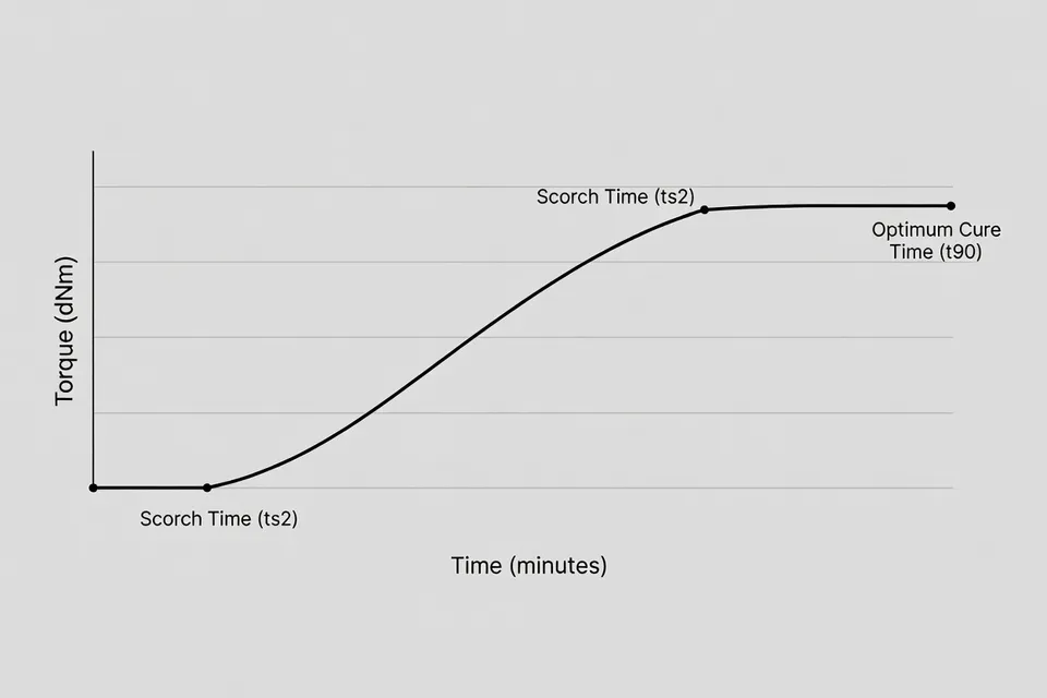
Moisture and volatile content also need a direct check when the defect is blistering or porosity. A mold can have clean vents and still produce internal defects if the compound condition or cure kinetics are wrong. Conversely, a cure curve that looks normal does not clear a cavity with trapped air. The defect location and the material data must agree before release.
The release decision
For the next shift, use a three-part hold rule. Hold the run when the final-fill area is unknown, when the nearest vent or vacuum path is blocked, or when consecutive pressure curves and part weights no longer match the approved window. Hold it again when the current cure curve moves outside the compound baseline, when under-cure is suspected without a confirmed cure result, or when QA has placed the lot on review.
Do not approve a setup because one adjustment removes a surface mark. A slower final fill may reduce an air trap while increasing cycle time. A longer cure may improve one part while masking material variation. Neither adjustment proves root cause.
The check to run this shift is simple: make short shots to locate the final-fill point, clean and verify the corresponding air path, then compare consecutive pressure, weight, and defect records with the approved cure curve for the same compound. If those records do not line up, stop the press and keep the lot on hold.
Editorial Insights
- How do we prove that a suspected air trap is a venting problem rather than a filling problem?
- Make short shots at several fill percentages and identify the actual last-fill location before touching the press settings. Inspect the nearest vent, insert clearance, ejector-pin vent, vacuum port, hose, gate, and runner for restriction or contamination. A pressure increase is not a diagnosis: if the flow front has moved because of a blocked gate or unstable shot volume, the original vent may simply no longer serve the cavity. The common failure is to confirm that a vent groove exists and mistake that for a verified air path.
- When is slowing the final injection speed a valid correction for an air-related defect?
- Use slower final fill only after the air path has been cleaned and verified, and only within the approved pressure, cycle, and flash window. It may give displaced air more time to escape, but it cannot restore a damaged vent, clear a restricted vacuum hose, or correct a gate problem. Record actual speed, injection time, pressure curve, shot weight, flash, voids, and dimensions across consecutive cycles. The usual mistake is to use a slower fill to keep a marginal mold running while the underlying restriction worsens.
- Which records should be compared before deciding that a pressure change is caused by the mold?
- Compare the actual pressure-curve shape and peak pressure with injection time, actual speed, shot weight, finished-part weight, flash, surface condition, internal voids, dimensions, and rejection rate. Stable weights with a changed curve point investigation toward venting, gates, mold temperature, or pressure response; moving weights require feeding and shot-volume checks first. Controller setpoints alone are not enough. A frequent misread is to blame trapped air when unstable metering has changed the amount of compound entering the cavity.
- How should a suspected under-cure be confirmed before changing press dwell?
- Do not add dwell as the first response. Test the current lot against the approved cure baseline for the same compound, method, and process, comparing ML, MH, t10, and t90; check moisture or volatile content when blistering or porosity is present. If the curve falls outside the approved rheological window, quarantine the lot and send the data for disposition. A longer dwell can make a part appear better while masking changed curative activity, polymer condition, or material variation, so it does not by itself clear the compound.
- Can a normal cure curve release a part with voids or a surface burn?
- No. A normal cure curve clears neither a cavity with trapped air nor a blocked relief path. Match the material result to the defect location and verify the final-fill point, vent condition, vacuum path, pressure response, weights, and finished-part inspection. Conversely, a clean mold cannot compensate for a wet compound or cure behavior outside its baseline. The release error is treating one laboratory or visual result as sufficient evidence when the material data and filling records do not agree.
References
- 1.Plas-Fab. (2026, October 15). Rubber injection molding: Process, design, materials, and production validation. Plas-Fab.
- 2.Tasu Machinery. (2026, October 6). Rubber mold venting: Design, air-trap prevention and troubleshooting. Tasu Machinery.
- 3.Tasu Machinery. Rubber injection molding process monitoring guide. Tasu Machinery.
- 4.Alpha Technologies. (2026, October 3). Rubber manufacturing troubleshooting: A complete guide for process engineers. Alpha Technologies.
- 5.Chu Rubber. Custom rubber mold: Full guide to process and quality control. Chu Rubber.
- 6.IMAT EG. Rubber defects. IMAT EG.
- 7.Rubber Mexico. Injection mold design considerations for rubber parts: Complete guide. Rubber Mexico.
- 8.OTT Rubbertech. Rubber compression molding guide: Process, equipment and best practices. OTT Rubbertech.
- 9.Moldtech Rubber. Rubber molding defects. Moldtech Rubber.
- 10.YH Rubbertech. Rubber product quality inspection. YH Rubbertech.